Bradford White Blinking Codes: Status Light Chart by Control Type
Bradford White blinking codes change with the control. On atmospheric ICON heaters, one slow flash with a pause is normal, 2 flashes means a weak pilot or low thermopile voltage, 4 means the temperature limit tripped, and 7 is a gas valve fault on ICON V1 only. Count between the 3 second pauses.
Where do you read the status light on a Bradford White gas control?
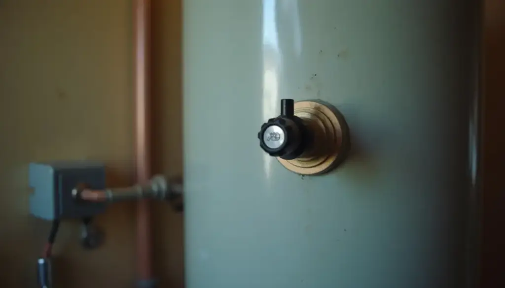
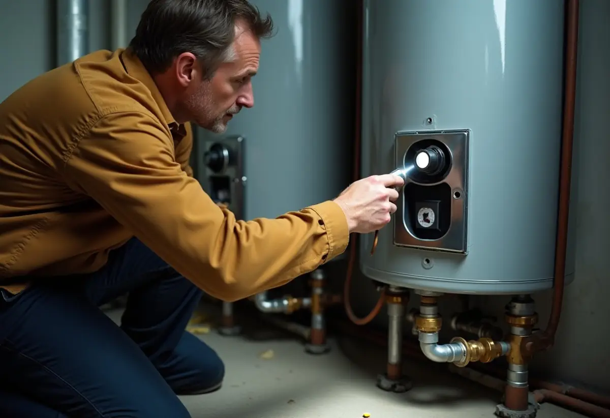
The status light sits on the face of the gas control at the base of the tank, to the right of the temperature knob on ICON V1 and V2. Bradford White’s Defender service manual 238-51542-00E says flash codes display with a three second pause before repeating, so wait for the pause and count one full group.
On V1, the ICON atmospheric quick guide 238-55948-00A lists “LED strobe (two quick flashes)” as a normal call for heat, while plain “two flashes” is the weak pilot fault. Film the light for 20 seconds if the rhythm is hard to judge. V2 and SIT use timing instead: 1 flash every 4 seconds with the burner off, 1 every second with it lit.
Is your Bradford White ICON, Defender or non-ICON?
ICON and non-ICON describe the gas control, while Defender describes the vapor-resistant combustion chamber, so one heater can be both ICON and Defender. Match the base of your tank against the control drawings in manual 238-51007-00R, summarized here, then use only the matching entries below.
| What you can see | What it is | Which codes apply |
|---|---|---|
| Round status lens upper right, silver or grey faceplate | ICON V1 (Resideo, Honeywell in a 2015 manual) | V1 entries, codes up to 8 |
| Square status window upper right, “ICON System” across the top, light or dark grey faceplate | ICON V2 (Resideo) | V2 entries, LED turns green, yellow or red |
| Wider housing, knob upper left, small status lens mid-body, white or grey label | ICON SIT (07/26 manual); same codes appear as “White Rodgers Electronic” in the 08/22 manual | SIT entries, code 5 is the highest |
| Round dial, no status light, no ICON mark | Non-ICON mechanical White Rodgers | None, it cannot blink |
| Power switch on the control or a cord to a 120 volt outlet, blower or damper on the vent | Powered family: Power Vent, Power Direct Vent, fan assisted, ULN D Series | Powered chart further down |
| Outer burner door, then a sealed inner door carrying a resettable thermal switch | Defender Safety System, not a control. Pairs with the first four rows | No code of its own on atmospheric models |
The rating plate settles a doubtful case: RG240T and LG255H are atmospheric, RG2PDV50S falls under the PDV manual 238-51541-00C, and URG1D30T under the D Series manual 238-51673-00D.
Bradford White status light chart for atmospheric ICON heaters
Eleven patterns cover atmospheric ICON controls, and 3 of them are not faults. This merges Bradford White’s separate charts from manuals 238-51542-00E (pages 8 to 11) and 238-51007-00R (pages 22 to 24), because the same count can differ between V1 and V2.
| LED pattern | Meaning per Bradford White | First step | Who does it |
|---|---|---|---|
| No light | Pilot not lit, no millivolt power to the control | Light the pilot from the label. If it will not stay lit: pilot assembly, then gas control | Owner, then technician |
| 1 flash, 3 second pause (V1). 1 green flash every 4 seconds (V2, SIT) | Normal: pilot lit, burner off | None, unless the knob still sits at PILOT | No one |
| 2 quick flashes, 3 second pause (V1). 1 green flash every second (V2, SIT) | Normal: thermostat calling for heat | None | No one |
| Solid on: green (V1, SIT), red (V2) | Knob recently turned to OFF, not an error | Wait until the LED goes out before relighting | Owner |
| 2 flashes, 3 second pause (yellow on V2) | V1: weak pilot signal, clears itself once the flame recovers. V2, SIT: low thermopile voltage, burner off | Look for a steady pilot, check thermopile wires | Owner looks; technician measures |
| 3 flashes, 3 second pause | V1 only: no temperature rise in the expected time | Confirm no hot water is running, then test probe ohms | Owner, then technician |
| 4 flashes, 3 second pause (red on V2) | Temperature limit reached, control locked out | Knob to OFF, wait 5 minutes minimum, relight, lower the setpoint | Owner once; technician if it returns |
| 5 flashes, 3 second pause (red on V2) | V1: temperature sensor fault. V2, SIT: electronics, sensor or gas valve fault | Check the control is dry and connections tight | Technician |
| 6 flashes, 3 second pause | V1 only: accessory module found water, if one is fitted | Check the drain pan, T&P valve and water fittings | Owner, then plumber |
| 7 flashes, 3 second pause | V1 only: gas control electronic fault | Check it is dry, then knob OFF, PILOT, relight | Owner once, then technician |
| 8 flashes, 3 second pause | V1 only: pilot stays on at OFF, pilot valve stuck open | Try OFF to PILOT once. If it still burns at OFF, close the gas supply valve | Licensed gas pro |
A V1 chart misleads on a V2 control. V2 and SIT stop at 5 flashes and fold several V1 faults into that code, and the V2 chart’s remedy for codes 4 and 5 ends at “Replace gas control,” so a repeat of either is a parts decision.
Ask for 2 readings before anyone sells you a control. Open circuit thermopile voltage should be 350 to 850 mV; a low reading sends the technician to the thermal switch test, then the pilot assembly. On codes 3, 4 or 5, sensor resistance should be 8,449 ohms at 84°F or 3,758 ohms at 120°F, taken with pin-type probes because standard probes damage the connector. Our gas control valve guide walks through the order of those tests.
Weigh the tank’s age first: decode the serial number, since its first 2 letters give year and month. Procedure RG-VI drains the heater completely for a valve swap, and procedure RG-X needs the level only below the outlet nipple to check the anode rod.
What does a Bradford White blinking 7 times mean?
Seven flashes means a gas control electronic fault on atmospheric ICON V1 and a flammable vapor sensor fault on powered models; the V2 and SIT charts list no 7 flash code. It is not a failed ignition lockout, as some pages claim: failed pilot lighting is 6 flashes then 1, on powered models only.
On V1, manual 238-51007-00R gives 3 steps: verify the control is not wet or physically damaged, turn the knob to OFF and then PILOT and light the pilot, and replace the gas valve if the code returns. A control that has been under water goes straight to a technician, per the lighting label.
On a Power Direct Vent, the control shuts everything off when sensor resistance passes 70,000 ohms, rechecks at 30 seconds, then retries on a 2 minute delay 5 times before a lockout, per PDV manual pages 9 and 11. The D Series chart adds other causes for code 7: vapors actually present, a sensor exposed to moisture or extreme ambient temperature, and an open resettable thermal switch.
Look first for gasoline, paint thinner or solvent near the heater. If you smell vapors or gas, leave and call the gas supplier or 911 from outside; otherwise clear them before touching power. Never unplug, jumper or bypass the vapor sensor. If a technician reads it outside 3,000 to 48,000 ohms with pin probes, the manual’s fix is a new sensor.
Power vent and direct vent Bradford White flash codes
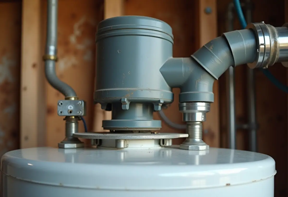
Powered models use a different code set in which only code 4 keeps its atmospheric meaning, per Bradford White’s power vent, power direct vent and fan assisted guide 238-55968-00A. A lost pilot has its own code only here, as 6 flashes then 3.
| LED pattern (3 second pause) | Meaning | First step (qualified provider) |
|---|---|---|
| No LED | No power or switch off | Turn power on, verify 120 volts at the outlet |
| Short flash every 4 seconds; bright and dim alternating | Standby; calling for heat. Both normal | None |
| Short flash once per second | Weak pilot on the last call for heat | Clean the pilot, check flame sensor continuity |
| 2 flashes | Pressure switch not working, closed position | Inspect pressure switch tubing and ports |
| 3 flashes; 6 flashes, then 2 | Pressure or temp switch stuck open; opened while running | Check the vent for blockage and the blower speed |
| 4 flashes | High tank temperature | Reset, then compare probe ohms to the sensor chart |
| 5 flashes; 6 flashes, then 4 | False pilot flame, pilot valve stuck open | Check for a flame sensor short, replace the valve if stuck |
| 6 flashes, then 1 | Pilot failed to light, auto resets | Clean the pilot, verify gas flow |
| 6 flashes, then 3 | Pilot flame lost, auto resets | Clean the pilot, check combustion air and gas pressure |
| 7 flashes; 8 flashes, then 1 | Flammable vapor sensor or simulated resistive device fault; out of spec | Verify no vapors, test 3,000 to 48,000 ohms, check harness |
| 8 flashes, then 2 | Thermowell sensor damaged or unplugged | Compare probe ohms to the sensor chart |
| 8 flashes, then 3 or 4 | Gas valve electronics or valve fault | Interrupt power once, replace if it persists |
The D Series differs: standby is one short flash every 2 seconds, codes 2 and 3 point to the damper circuit, and 9 flashes then 1 means insufficient combustion air. These charts are written for qualified providers; an owner’s share is the switch, a lamp test at the outlet and the vent terminal.
How does Bradford White say to reset the control after a code?
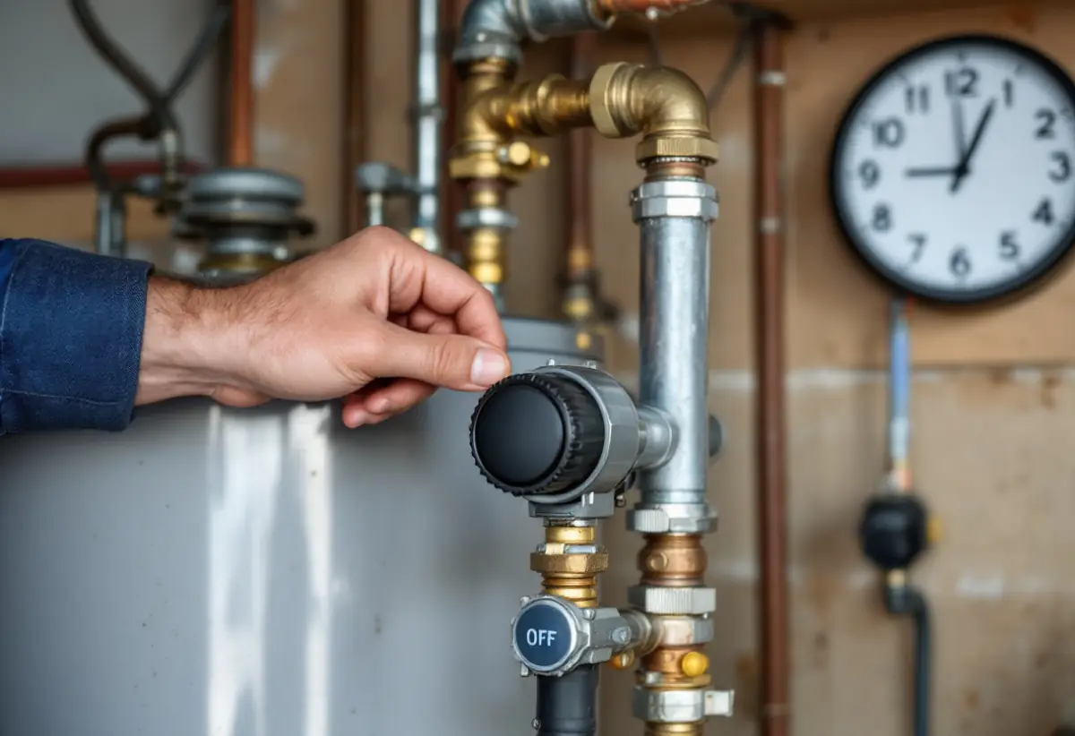
An ICON control has no reset button: for code 4 Bradford White says to turn the knob to OFF, wait at least 5 minutes and relight from the label. Codes 2 and 3 on V1 clear themselves. The Resideo label on page 16 of 238-51007-00R gives the relight:
- Set the knob to OFF by hand, never with tools. Wait 5 minutes, then smell near the floor. If you smell gas, stop, leave the building and call the gas supplier from a neighbor’s phone, or 911 from outside.
- Remove the outer door, then remove the inner door or slide it open. Never light the pilot by hand.
- Turn the knob clockwise to PILOT, then push and hold it.
- Press the igniter until it clicks, and keep holding until the status light blinks. Gas can take up to 15 seconds to flow after the pilot lights.
- Release. The knob should pop back out and the pilot should stay lit. Replace both doors and set your temperature.
Call a technician if the knob does not pop out, or the pilot fails after several tries. Our guide to relighting a water heater pilot covers repeat outages. If code 4 returns, procedure RG-VI on page 30 moves to testing the temperature sensor.
Codes 8 then 3 and 8 then 4 call for interrupting the power supply, and the vapor lockout is listed as “Indefinite (cycle power to restart).” The PDV manual prints two code 4 resets: page 12 says hold the knob at minimum for 6 seconds, page 25 says OFF for 5 minutes. Use page 25, headed “ECO Reset,” and call Bradford White technical support at 800-334-3393 with your model and serial numbers if it does not clear.
Why doesn’t an atmospheric Defender heater show a vapor lockout code?
Atmospheric Defender models have no vapor sensor in manual 238-51542-00E: a flame arrestor plate holds flame inside the chamber, and a thermal switch shuts down the pilot and main burner. A tripped Defender shows up as a pilot that will not stay lit, and a 2015 Bradford White chart also lists an open thermal switch under 2 flashes.
The switch has a button at its center and opens at about 240°F (blue), 270°F (yellow) or 290°F (red), depending on model. Bradford White says to find the overheating condition before returning the heater to service. The listed causes are starved combustion air, a weak or wrong switch, and a flammable vapor incident, whose correction is “Replace water heater.” Ask for the jacket slots and arrestor plate to be inspected first, under procedure RG-IX.
Never run the heater with the inner door off or the switch held closed. Page 35 warns that removing the inner door deactivates the Defender system, and fire or explosion can follow if vapors are present.
Frequently asked questions
Why is my Bradford White water heater blinking green?
A green blink is normal on ICON V2 and SIT controls. One flash every 4 seconds means the pilot is lit and the burner is off. One flash every second means the burner is lit and heating. Neither one is an error, so nothing needs a reset.
What does a yellow or red status light mean on a Bradford White?
Only ICON V2 changes color. Yellow with 2 flashes means low thermopile voltage. Red with 4 flashes means the temperature limit tripped, and red with 5 flashes means an electronics, sensor or gas valve fault. Solid red is not an error, because it only shows the knob is at OFF.
Does a Bradford White water heater have a reset button?
The ICON control has none, so its reset is done with the knob. Defender heaters do have a button at the center of the resettable thermal switch on the inner door. Bradford White says the overheating cause must be found before that heater returns to service.
Can a Bradford White gas control be reused after a flood?
No. The lighting label says not to use the heater if any part has been under water. A qualified technician must inspect the appliance and replace any part of the control system and any gas control that was submerged, even if the status light still blinks normally.
How we sourced this
We read the Bradford White documents named above, plus a 2015 FVIR manual, viewing charts and drawings as page images. Meanings are Bradford White’s; the merged charts, identification table and “who does it” column are our reading of those documents. Repair prices and a 10 flash code seen on third-party sites are left out because no Bradford White document we opened supports them. Tankless and electric models are excluded.